This is a reflection of my time from 2020-2022
You can just build an electric car
Yes, I mean you. 🫵
You can just do things. You can even build an electric car.
The people who build electric cars are no smarter than you. Just do it.
Our car, Purple Haze, used an EMRAX 228 high-voltage motor, a DTI HV500 inverter, a welded 4130 steel frame, custom suspension and brakes, and 448 cylindrical lithium-ion cells.
At the report's 470.4 V and 180 A design point, the battery could theoretically deliver 84.7 kW, or about 114 electrical horsepower before losses. Competition rules capped motor draw at 80 kW anyway. Also, we did not have airbags, so nobody volunteered to find the true top speed.
| Specification | Purple Haze |
|---|---|
| Cells | 448 Molicel P42A 21700 cells |
| Pack | 4p112s, split into four 4p28s segments |
| Maximum voltage | 470.4 V design figure |
| Peak design current | 180 A system-level target |
| Accumulator mass | Roughly 150 lb |
| Motor and inverter | EMRAX 228 HV and DTI HV500 |
Bench-spinning the motor before it had a car.
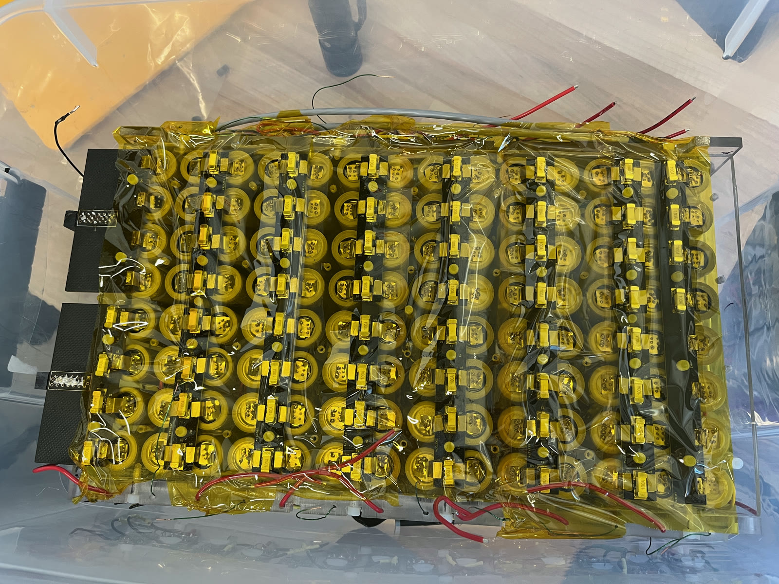
One 112-cell segment with its fuse boards installed.
Purple Haze placed fourth overall at Formula New Hampshire and won the IEEE Excellence in EV Engineering Award. I am especially proud of my individual-contributor work on the battery and my role as co-captain building the electrical teams.
When batteries become serious business
A small battery is a source, a switch, and a load. At 470 V, every extra box exists because something expensive or dangerous happens without it.
The 448 cells fed service disconnects and a main fuse, then the Accumulator Isolation Relays, inverter, and motor. A smaller precharge path protected the inverter's capacitors at startup. The AMS watched the cells and could command the shutdown circuit to open the relays.
The inverter's discharged capacitors initially look almost like a short circuit. Slamming the main contactors can create a huge inrush and weld them together. Precharge closes a smaller path through a resistor first, filling the capacitors gently before the main relays close.
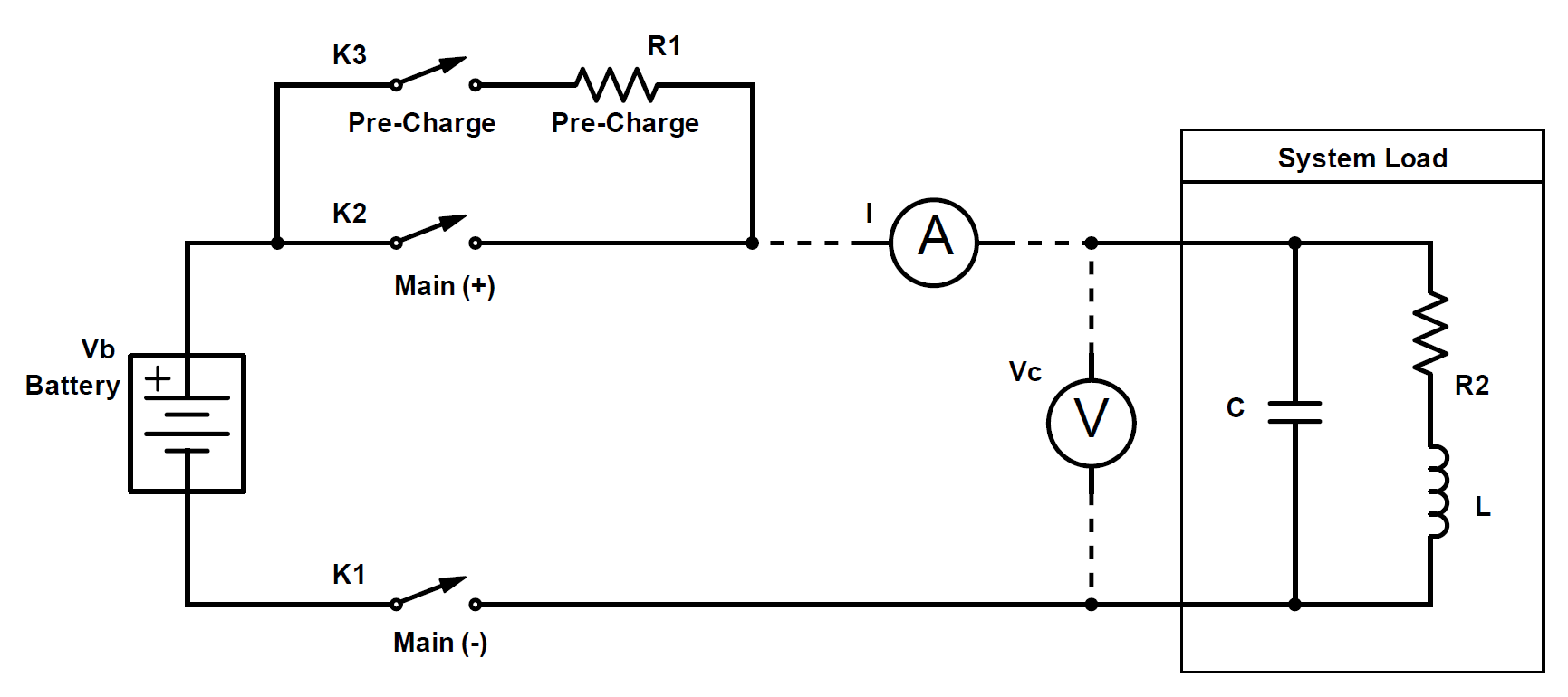
Think of opening a water valve slowly so the downstream pipe fills without a pressure shock. After shutdown, the discharge circuit is the drain: it bleeds energy out of those capacitors so the car does not remain dangerously charged.
The AMS watched 112 groups at once
Cells do not age identically. One group can reach a dangerous voltage or temperature while the pack average still looks fine.
Our EMUS Accumulator Monitoring System used four isolated group modules and 112 cell modules, one for every four-cell parallel group. It watched voltage, temperature, and pack current, and balanced groups during charging.
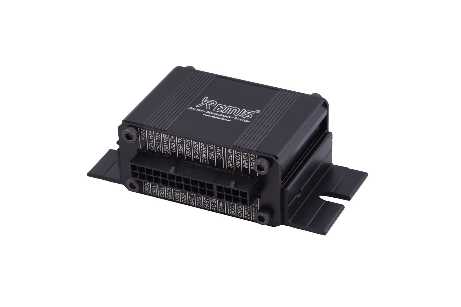
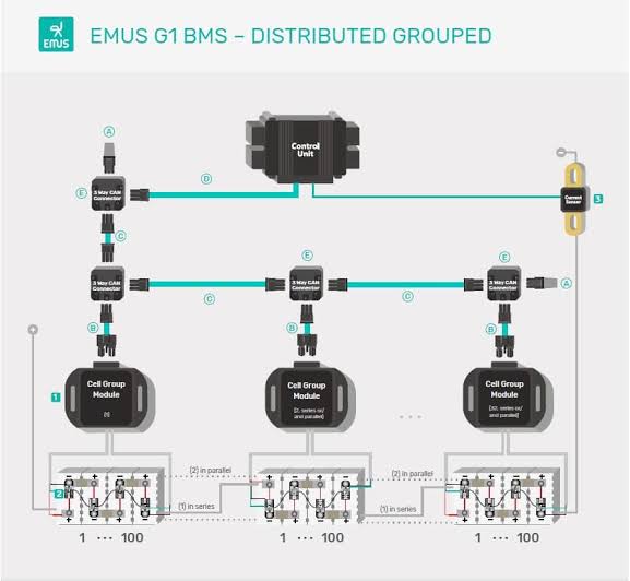
If a group left its safety envelope, our support board latched the shutdown circuit and removed power from the relays. The AMS detected the problem; the shutdown circuit issued the command; the relays physically disconnected the car. Fuses handled faults that moved faster than software could.
Fusing: the tiny parts that almost stopped the car
Two fuse layers, two different jobs
The main fuse sees current leaving the accumulator, so it protects the car-scale circuit: contactors, cables, inverter, and pack during an external short. A failed cell creates a smaller loop inside its four-cell parallel group; three healthy cells can feed it without that current ever crossing the main fuse. Cell links isolate that local failure.
The main fuse protects the car from the battery. Cell fuses protect the cells from each other.
There is such a thing as the wrong kind of safe
At our 180 A target, four parallel cells supplied 45 A each. Choosing a 45 A fuse for every cell sounds conservative. The competition rule coupled those links to the main fuse:
I_main ≤ (N_parallel × I_cell-fuse) / 3With four 45 A links, the main fuse could be only 60 A. That was enough to make the car very safe by making it barely move.
After working through the fault paths with competition officials, we sized backward from a practical 125 A main fuse:
I_cell-fuse ≥ (3 × 125 A) / 4 = 93.75 AWe sourced a 100 A surface-mount cell fuse, which permits up to 133.3 A under the same relationship and leaves room for a 125 A main fuse.
The unintuitive lesson was that a higher-rated cell fuse enabled the correct pack-level protection. More conservative numbers are not automatically safer; every protection device needs a specific fault to own.
A cell fuse has three jobs
1. Carry normal current
At 40 A, even one milliohm turns into 1.6 W of heat:
P = I²R = 40² × 0.001 = 1.6 WThat is a lot for a tiny piece of metal attached directly to a lithium-ion cell.
2. Melt in the right place
I tried triangular cuts, drilled holes, and punched holes in nickel strip. Thin nickel stretched, shredded around drill bits, and curled after punching. A geometry I could calculate once was not necessarily one I could manufacture hundreds of times.
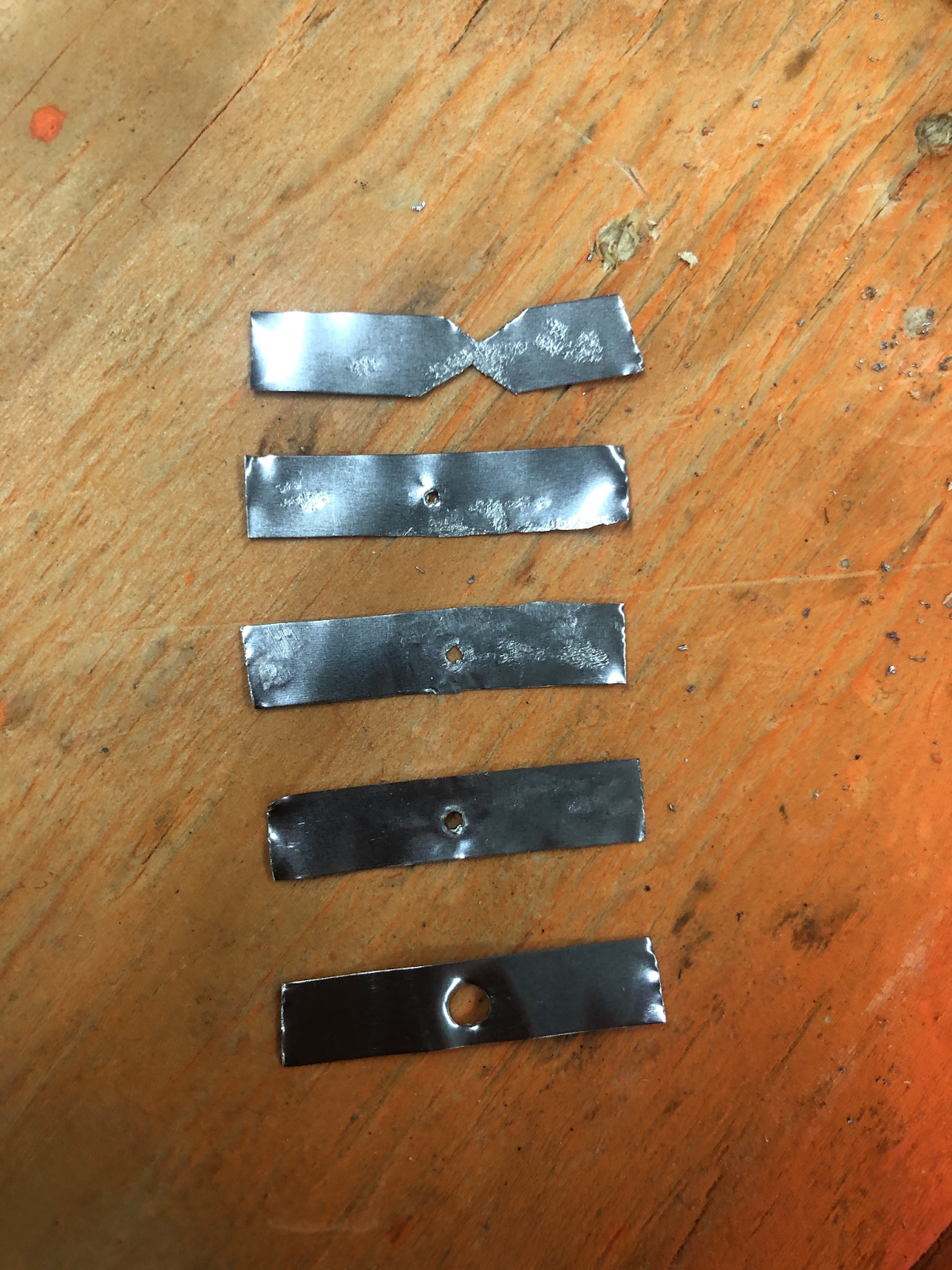
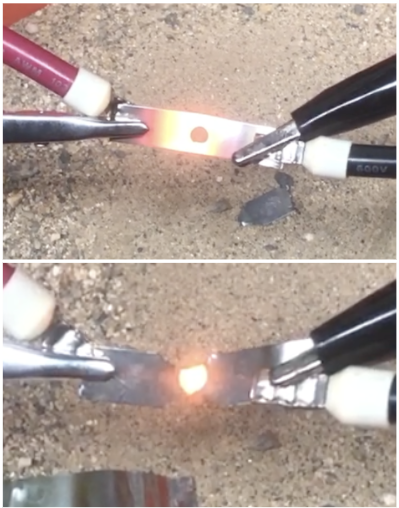
We ramped current from a 5 kW supply and watched where each link glowed. The comparison was not controlled enough to select a winner, but it showed what to model next. Nico Machado then screened a 0.5 mm nickel geometry in COMSOL at 40 A and 120 A.
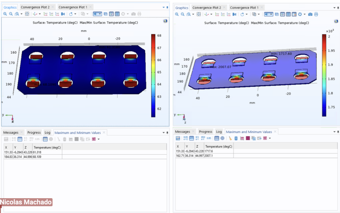
The steady-state model predicted acceptable normal heating and melting at the fault current. It could not predict time-to-open or certify assumptions about airflow inside a pack that did not exist yet.
3. Stop conducting after it melts
Opening the metal does not guarantee the current stops. Inductance creates a voltage spike that can arc across the new gap, the electrical version of water hammer in a pipe.
A fuse has to open twice: mechanically by melting, then electrically by ending the arc.
We measured ten P42A cells at an average internal resistance of 9.26 milliohms. At maximum cell voltage, our simplified short-current estimate was:
I_short = 4.2 V / 0.00926 Ω = 453.6 AThe link had to interrupt roughly 453 A without throwing heat, sparks, flame, or debris into neighboring cells.
Side quest: could the cell protect itself?
I heard a rumor that the P42A had an internal fuse, so I destructively opened one. I found insulation and a thin copper braid, but no obvious discrete fuse. The result was inconclusive, so it did not change the external-fusing plan. But it was fun to smell some lithium.
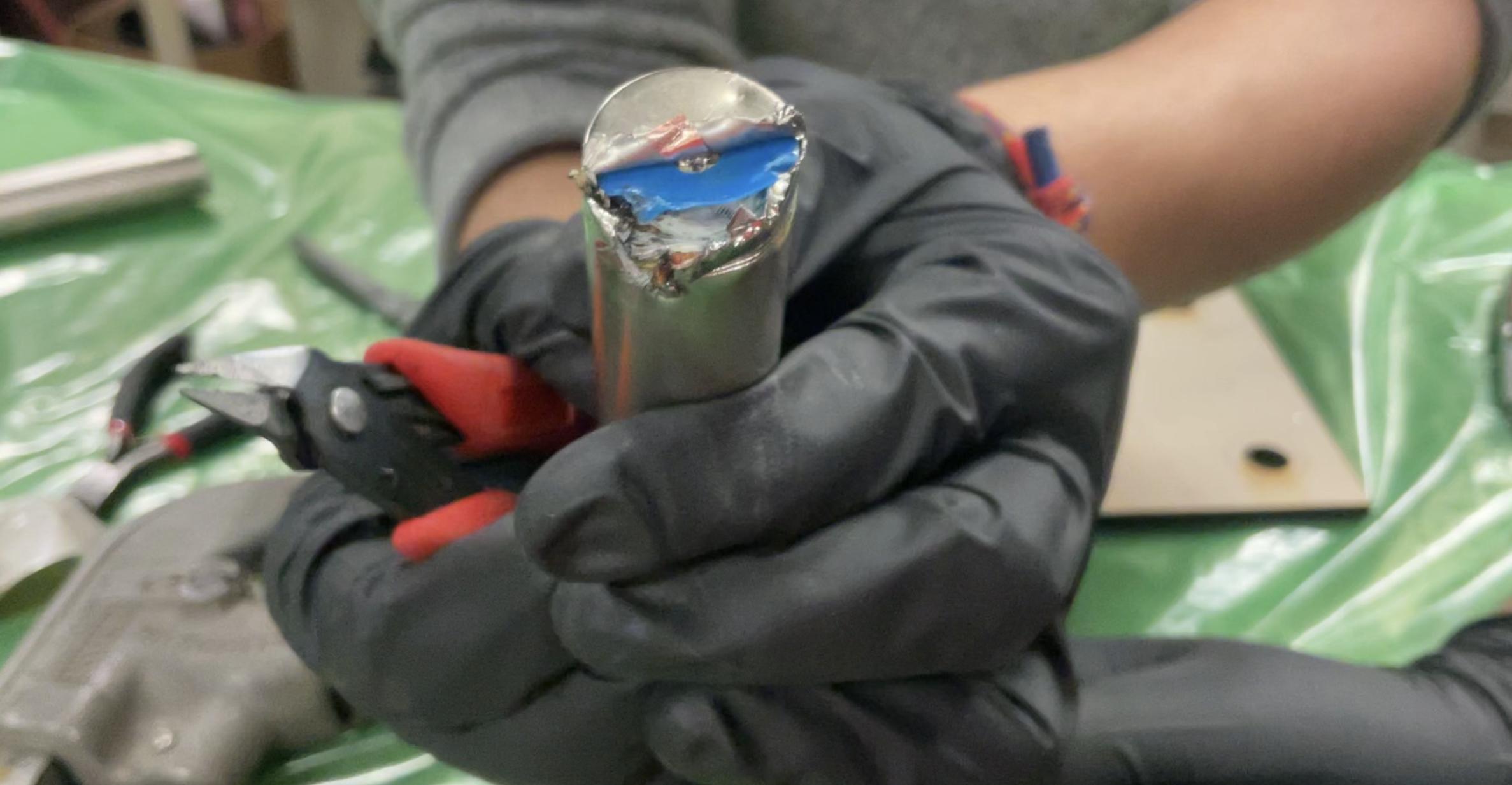
Safety note: The LG engineer I met at the race was horrified whe he saw I did this in just nitrite gloves.
The test rig became part of the design
Nico and I tag-teamed the fusing work, but the capacitor bank was his idea and his rig. His 32 mF capacitor bank, 100 V/100 A supply, relay, and Hall sensor produced a pulse above 600 A. It still failed the test: the pulse did not last the tens of milliseconds needed to open the fuse. A thermal test passed by about 5°C, but that margin was comparable to the camera's uncertainty.
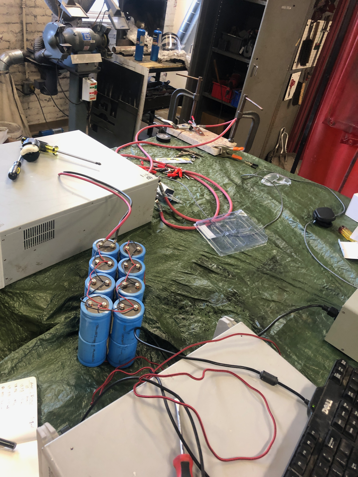
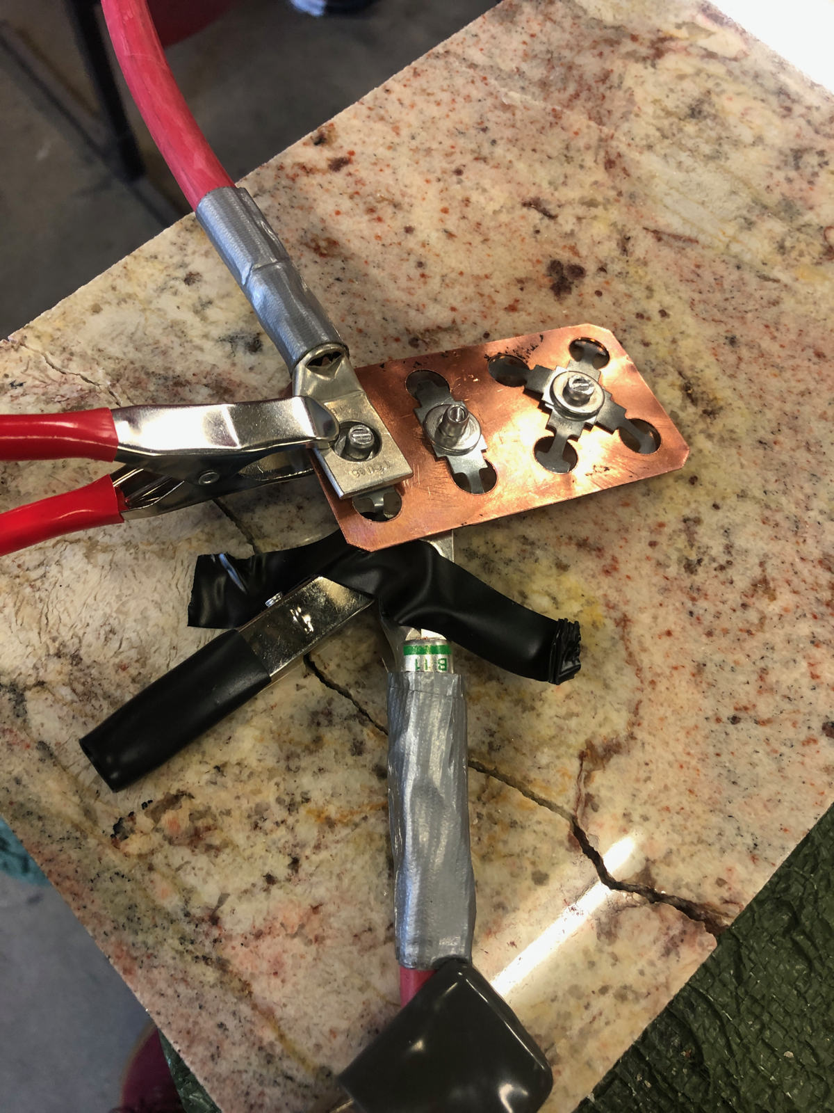
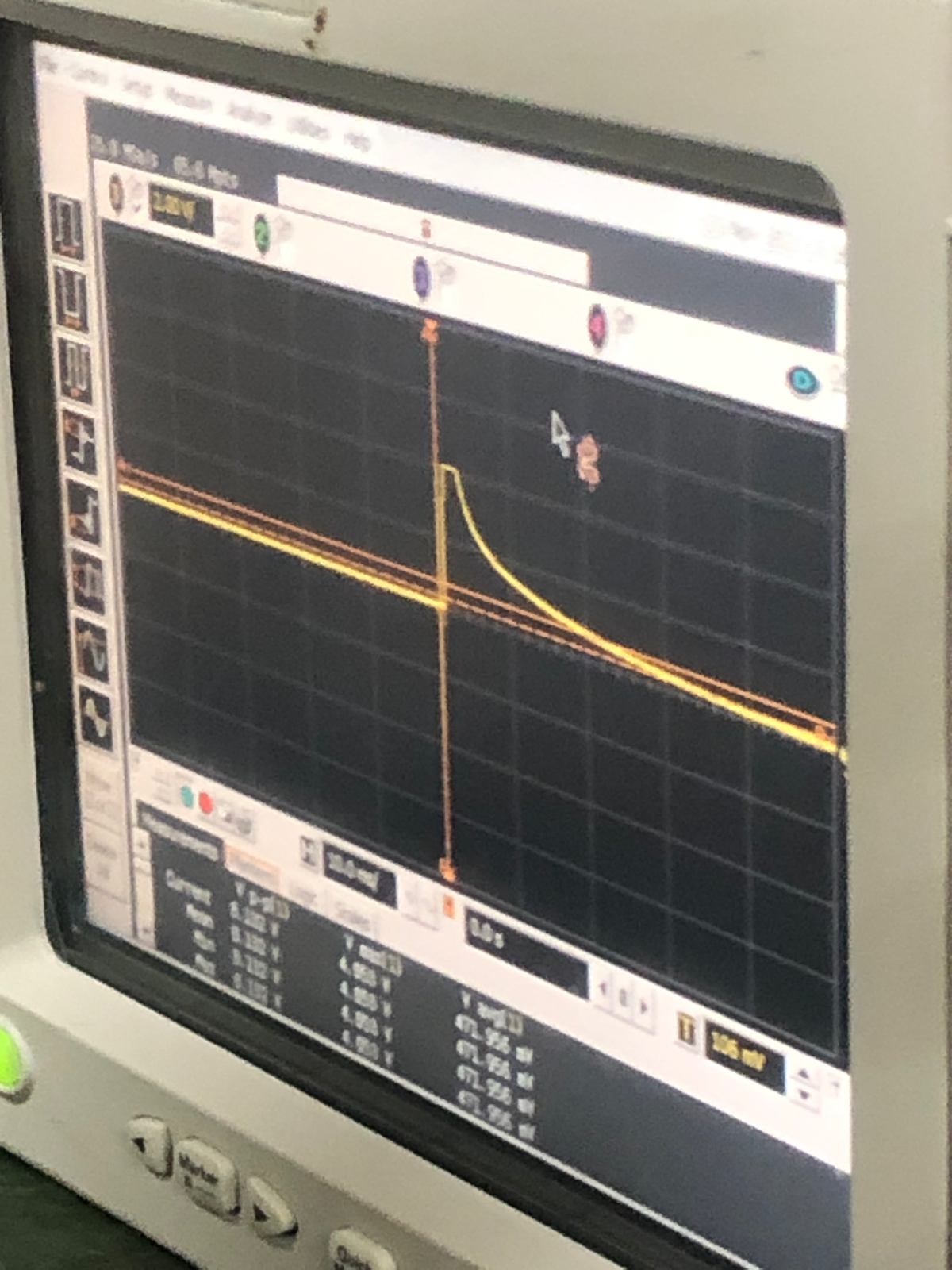
A test you cannot measure accurately is mostly a story you are telling yourself near expensive hardware.
Then we had to attach it 448 times
Commercial fuse clips were too tall. A zinc-alloy strip fuse fit better, but modifying its mounting and thermal environment meant its datasheet rating no longer answered the whole question.
Laser welding failed because the zinc alloy disappeared hundreds of degrees before the copper bus bar melted. Riveting avoided the heat but added resistance and assembly problems. Spot welding to the cell either made no connection or incinerated the fuse.
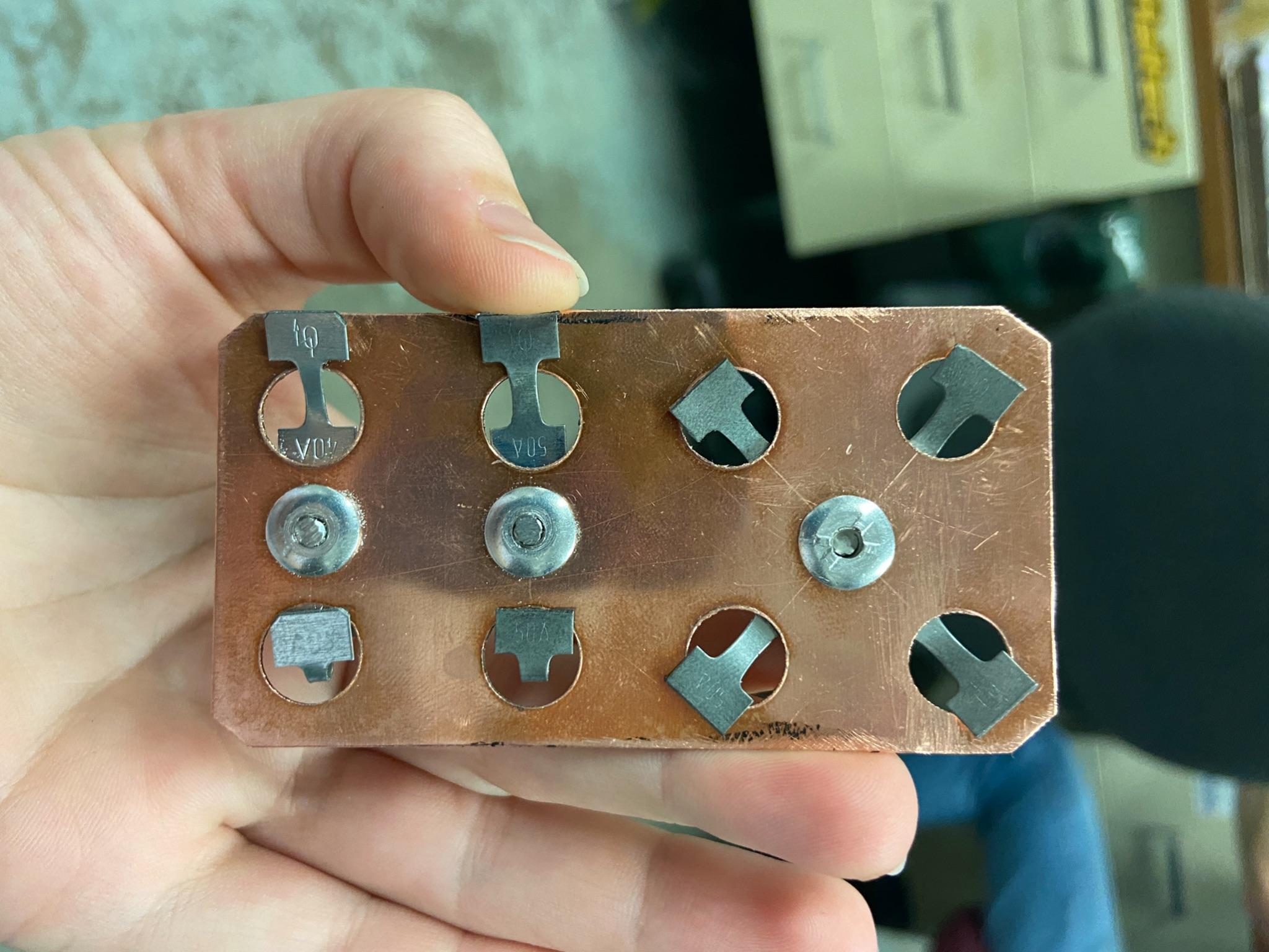
Iteration three: riveted commercial strip fuses on a copper bus bar.
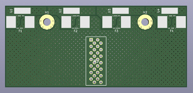
Final documented direction: modular boards with surface-mount fuses.
Aluminum wire bonding was elegant, but it required sourcing the bonder before finalizing the collector plate, fixture, and bond-head clearances. We did not have that time.
The design moved to modular PCB fuse boards. A Python script generated an entire segment-sized board, but code could not fix the quote, thermal mass, reflow-oven envelope, or serviceability. Smaller middle, edge, and bridge boards cut assembly from weeks to days.
Then the battery tabs drifted during reflow and landed on the fuse contacts. We fixed them by hand.
Engineering is sometimes using simulation, scripting, and automated assembly to create a problem that you repair one component at a time.
The final design direction used surface-mount fuses sourced from Eaton.
I spent days cold-calling regional managers until a kind manager in Massachusetts sent us $3,000 worth of fuses.
Thank you, David. I think of you often.
Lessons On Doing Big Projects
1. Referrals over interviews.
The best hit rate for interviews is like 60%. Find friends and work with your friends.
2. Get the admin sh*t right
We almost missed the competition because of fusing (and many other close call subsystems). Solving it meant more than electrical engineering.
I spent:
- Weekends emailing distributors for stock
- Lunch and dinners cold-calling sales managers for free or discounted parts
- Stayed up until 3am multiple nights doing paperwork so people could join the project
Get the admin sh*t right.
3. It's a team project.
It's we not you, always. Don't forget you're on a team.
Big thank you to everyone below and especially:
- Jesssica Babcock, Nico Machado, Oliver Thode and Gabriel Dudlicek.
So thankful they put up with me as long as they did.
https://wp.wpi.edu/wpifsae/current-mqp/